
In honor of our seventeenth anniversary, we invite you to take a look at some major research developments and trends in antenna history over the past century.
1920s: Yagi-Uda Antennas
In 1926, Japanese inventor Shintaro Uda, with the help of his colleague, Hidetsugu Yagi, developed the Yagi-Uda antenna. Modern versions of this antenna are used on high frequency (HF), very high frequency (VHF), and ultra high frequency (UHF) bands due to its characteristically high gain.
The directional antenna is primarily an array of linear dipoles with one driven element serving as the feed while additional elements act as “parasitic.” While the feed element is connected to the transmitter or receiver with a transmission line, the additional elements are unattached. The purpose of these parasitic elements (or passive radiators) is to modify the radiation pattern of the radio waves emitted by the driven element, directing them in a beam in one direction. This increases the the antenna’s directivity and consequently, its gain.
Today, this style of antenna is commonly known as the “beam antenna” or the “parasitic array.” However, many still refer to it as the “Yagi antenna.” This is perhaps due to the fact that while Uda was mainly responsible for the antenna’s invention, it was Yagi who helped popularize the antenna in the United States.
1930s: Horn Antennas
A relatively simple and widely used antenna, the horn antenna, can date its origins back to the late 1800s. However, it wasn’t until decades later, during the World War II era, that it became popular. In 1938, American inventor Wilmer Lanier Barrow invented the first modern horn antenna, following his invention of the waveguide in 1936.
Horns can be used in a variety of different applications due to their ease of use and their ability to achieve large gain. As an added bonus, they feature relatively simple construction, which makes them generally cost-effective. An example of an efficient, yet simply constructed modern horn antenna is the JEM-440.
The modern electromagnetic horn can take many different forms, four of the most popular being E-plane, H-plane, pyramidal, and conical. The differences in type, direction, and amount of taper are variables that augment a horn antenna’s overall performance as a radiator.

1960s: Dish Antennas
The “satellite dish” is perhaps the most recognizable type of antenna among consumers. It’s classified as parabolic reflector, a type of antenna which gets its name from its curved surface (parabola). Although the earliest version of the parabolic reflector antenna was developed in 1888 by German physicist Heinrich Hertz, it wasn’t until the 1960s that these types of antennas became commonplace.
Besides satellite television, parabolic antennas are used as high-gain antennas for point-to-point communications, in applications such as microwave relay links that carry telephone and television signals between cities, wireless WAN/LAN links for data communications, and satellite communications. These antennas have also been useful in spacecraft communications for decades.
Additionally, parabolic antennas are widely used as radar antennas for locating ships, airplanes, and guided missiles.
1970s: Microstrip Antennas
Although they originated 1953, microstrip antennas started garnering plenty of attention in the 1970s. Also known as “patch antennas,” they are extremely useful in aircraft, spacecraft, satellite, and missile applications, as well as mobile radio and wireless communications, due to their characteristically low profile. They are also inherently lightweight, inexpensive to manufacture, and easy to install. The RFD-8696 is an example of a very versatile patch antenna.
The defining characteristic of the modern microstrip antenna is that they can be printed directly onto a circuit board.
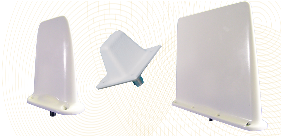
1980s: Planar Inverted-F Antennas (PIFA)
A form of patch antenna, the Planar Inverted-F antenna (PIFA) is a common component in handheld devices. It gets is name from it’s shape, which resembles an inverted “F.”
The PIFA resonates in an omnidirectional pattern. More importantly, it does so at a quarter-wavelength, allowing manufacturers to increasingly reduce the amount of space the component needs to occupy within a mobile device.
PIFAs also have favorable SAR properties. SAR is a a function of the electrical conductivity, which measures how transmitted RF energy is absorbed by human tissue. It stands for “Specific Absorption Rate.”
All of the aforementioned antenna designs are still being used today. In fact, because there have been numerous developments that improve upon their designs, they have even become more useful than they were when they were first invented. As antenna design continues to evolve at an even faster pace, it is important to quickly and efficiently test the resulted products.
Latest Posts

STEM with JEM
Did you know that National STEM Day falls on the 8th of November each year? That’s because the abbreviation “NOV8” actually stands for “INNOVATE.”
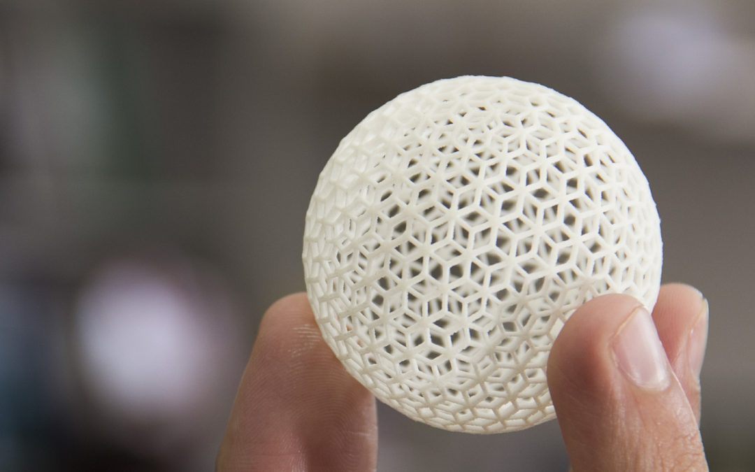
Reshaping Antenna Design with 3D Printing
As we discussed in a previous post, before we can manufacture, we must prototype. For this step in the process, we are beginning to explore additive manufacturing, or as it’s more commonly known, 3D printing.
An Overview of Unmanned Aerial Vehicles — and their Antennas
An unmanned aerial vehicle, or UAV, refer to a vehicle that is able to fly remotely, either with some sort of controller or autonomously. An unmanned aircraft system, or UAS, includes not only the UAV, itself but also the person on the ground controlling the flight, as well as the system in place that connects the two of them.

An Introduction to RF Testing
RF testing is used to measure a variety of different antenna attributes. In this post, we discus a few ways in which rf testing can help determine if your device is performing the way it should.

Antenna 101: Types & Applications
In this article, we take a look at some of the different antenna types, and what applications they can be used for.