Spiral Series: The Cavity-Backed Spiral
June 2025
Spiral Series: The Cavity-Backed Spiral
Spiral antennas are frequency independent antennas with some practical performance limits.
In a previous post, we introduced the spiral antenna as inherently circularly-polarized frequency-independent antenna which, as the name suggests, features spiral-patterned conductive elements. Spirals are considered frequency-independent antennas, mostly because their characteristics like polarization, radiation pattern, and impedance remain relatively constant over a broad range of frequencies. While frequency-independent antennas theoretically have no bandwidth limitations, a spiral antenna’s bandwidth is limited in the sense that they generally perform better at higher frequencies. At lower frequencies, the antenna’s radiation is concentrated at the outermost part of the spiral, while at higher frequencies, it’s concentrated near the center, where the current distribution is more uniform.
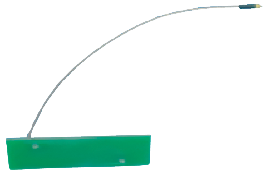
The cavity within a cavity-backed spiral antenna reflects backward radiation forward.
This cavity is placed behind the spiral arms, reflecting backward radiation forward, thus creating a unidirectional pattern. This controls how electromagnetic waves interact with the antenna structure, specifically enhancing radiation efficiency, directivity, and impedance stability at longer wavelengths.
Cavity-backed spirals are generally better suited for airborne applications.
The cavity backing provides more structural stability, adding more protection from physical impact. Additionally, it can act as a shield, protecting the internal components of the spiral antenna from moisture, corrosion, and other harsh environmental factors, making spiral antennas more suitable for airborne applications than standard spirals. For more information, check out our blogs on flight qualification and environmental testing.

Should you choose a cavity-backed spiral over a standard spiral?
While cavity-backed spirals offer advantages over standard spirals, as with all antennas, there are some factors to consider. Comparatively, standard spirals operate over a broader frequency range, making them more ideal for signal monitoring and broadband communications. Conversely, cavity-backed spirals are better for applications demanding higher gain and/or a narrower beam patterns, such as radar or direction-finding, as well as some EW applications. Essentially, the specific requirements of the application, such as bandwidth, gain, and beamwidth, will dictate which type of antenna is more suitable between the two.
There are also some design considerations to make when choosing a cavity-backed spiral over a standard spiral. For one, the design has to include proper cavity dimensions to avoid unwanted resonances and optimize gain. If the proper material isn’t selected for the cavity, the antenna can suffer from reduced efficiency. Also, they can be physically larger and heavier than standard spiral antennas.
JEM Engineering’s hybrid spiral antenna product line features several types of low-profile spirals that operate between 100 MHz to 18GHz. We can modify our existing products to our clients’ spec, as well as the expertise and manufacturing capability to develop custom spiral designs.
In the next post, we will continue our spiral series by introducing phase matched spirals antennas.
Latest Posts

Antennas for Maritime Applications
In this post, we will answer some of the most common questions regarding marine antennas.
Narrowband Antennas Vs. Wideband Antennas
In this post, we will be making some general comparisons between narrowband and wideband communications.
Dipoles: The Simplest, Most Common Antenna
As it’s name suggests, in its basic form, a dipole antenna consists of two conductive elements, unlike a monopole antenna, which has one.
Anatomy of a Vivaldi Antenna
The Vivaldi antenna, also known as a tapered slot antenna, is a type of linear-polarized planar antenna invented by Peter Gibson in 1978…
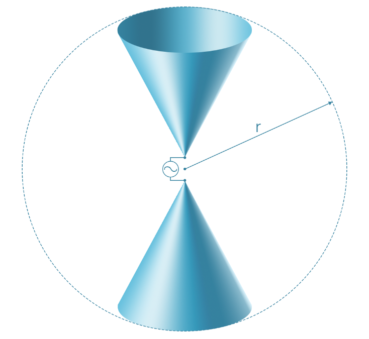
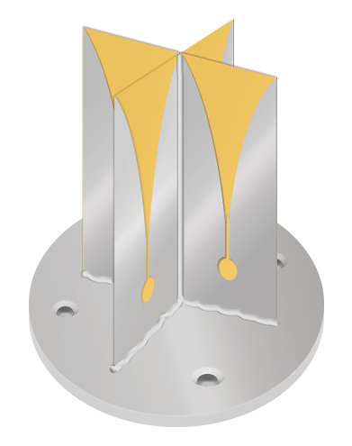
Introduction to the Biconical Antenna
The phrase “biconical antenna” describes a broadband antennas that are made up of two roughly conical conductive objects, that are nearly touching at their points. Because of their configuration, they can also be referred to as “bowtie” or “butterfly” antennas.