Microstrip Antennas: The Basics
September 2020
In a previous post, we introduced microstrip antennas. In this post, we explore their basic characteristics, benefits, and drawbacks.
Microstrip antennas were patented in 1955, although their origins trace back to 1953. They became more commonplace in the 1970s. The antennas consist of a very thin metallic radiating element, or a “patch,” placed small fraction of a wavelength above a ground plane.
There are various substrates used in designing microstrip antennas, Thicker substrates with lower dialectric constants deliver larger bandwidth and better efficiency, while thinner substrates with higher dialectric constants are better or microwave circuitry.
Microstrip antennas have many benefits.
The most notable benefit of microstrip antennas is their versatility. Firstly, they are small and lightweight, as well as easily conformable to planar and nonplanar surfaces. Additionally, they can be are mechanically robust when mounted onto rigid surfaces. Thus, they can be used in an various applications, including aircraft, spacecraft, satellite, missile, mobile radio, and wireless communications.
Another benefit of microstrip antennas is that they are simple and inexpensive to manufacture. These low-profile antennas can be printed directly onto a circuit board.
But they have their drawbacks.
Micostrip antennas do have their disadvantages, one of which is their low efficiency. They also have low power, poor polarization purity, poor scan performance and faulty feed radiation. Additionally, these antennas have very narrow frequency bandwidth, which may be a benefit for some government security systems.
While there are ways to correct some flaws, doing so can negatively affect the antenna’s performance in other ways. For example, increasing the height of the substrate can extend the antenna’s efficiency. However, as the height increases, more surface waves will travel through the substrate, scattering at bends and surface discontinuities, degrading the antenna’s pattern and polarization characteristics. Similarly, while there are ways to increase the bandwidth, in large arrays, there would be a trade-off between bandwidth and scan volume.

Shapes do matter.
Patch elements of microstrip antennas come in various shapes and modes (field configurations), which affect the antennas’ resonant frequency, polarization, radiation pattern, and impedance. These factors are further influenced by adding loads, such as pins and varactor diodes, between the patch and the ground plane.
Square, rectangular, dipole,and circular are very common because they are the easiest to manufacture and analyze. They also have favorable radiation characteristics, especially cross-polarization radiation. Dipoles, in particular, inherently have large bandwidth and occupy less space, making them attractive for arrays.
Linear and circular polarizations are achievable with either single elements or arrays of microstrip antennas. Arrays with either single or multiple feeds may also improve scanning capabilities and directivities.
Latest Posts
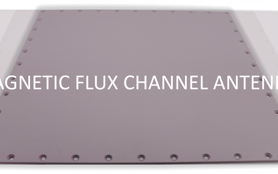
What is a Magnetic Flux Channel Antenna?
Years ago, JEM Engineering developed the Magnetic Flux Channel Antenna. Now, the company has a series of these types of antennas, nicknamed MFC Antennas.

An Introduction to Jammers
As the name suggests, jamming antennas, (aka jammers) are specifically used to interfere with radio noise or signals. In electronic warfare (EW) these interference are meant to disrupt control of a battle.

Antennas: A History
In honor of our seventeenth anniversary, we invite you to take a look at some major research developments and trends in antenna history over the past century.

Honoring Black Engineers
JEM Engineering is a minority owned company and in honor of Black History Month we would like to shine light on two Black engineers who have made an impact in the world of engineering.