Dipole Antennas: The Simplest, Most Common Antenna
August 2021As it’s name suggests, in its basic form, a dipole antenna consists of two conductive elements, unlike a monopole antenna, which has a single conductive element.
The dipole’s identical conductive elements (usually rods or metal wires) sit on either end of the antenna. While separated by a strain insulator, the center-facing ends of these two antenna sections are connected to a feed line or coaxial (RF) cable, which carries current in both the conductors. These currents are equal in magnitude but opposite directions, linking the radiating fields within the cable, and causing the fields to cancel each other out.
The current is maximum and voltage is minimum at the center of the dipole antenna. In contrast, the current is minimum and voltage is maximum at the ends of the dipole antenna.

The radiation pattern is perpendicular to the conductor of the antenna. This means that the dipole antenna radiates energy out into the space, perpendicularly to its axis.
There are many kinds of dipoles, but in this post, we will only describe two variations. A half-wave dipole, also known as a doublet, or the Hertz antenna, is the most commonly used type of dipole antenna. The length of its conductive elements is approximately half of the maximum wavelength (λ/2, the distance between two consecutive maximum or minimum points) in free space at the frequency of operation. A half-wave dipole’s current distribution is that of a standing wave, approximately sinusoidal (having the form of a mathematical sine curve) along its length.


While dipoles can be used standalone low-gain antennas, they can also be incorporated as driven elements in antenna designs such as the Yagi antenna and driven arrays.
They can be used to feed more elaborate directional antennas such as a horn antenna, parabolic reflector, or corner reflector. Additionally, engineers analyze vertical (or other monopole) antennas on the basis of dipole antennas of which they are one half.
JEM Engineering has experience designing dipoles suitable for HF, VHF, and UHF.
For example, the BCA-620 is a broadband dipole blade optimized for intelligence, surveillance and reconnaissance (ISR), as well as signal intelligence (SIGINT) applications, operating within frequencies from 600 to 2000 MHz.

Latest Posts
Which Testing Chamber? TATF vs. SNF
JEM Engineering boasts two antenna testing chambers at our facility in Laurel, MD, within easy reach of both Baltimore and Washington DC.

STEM with JEM
Did you know that National STEM Day falls on the 8th of November each year? That’s because the abbreviation “NOV8” actually stands for “INNOVATE.”
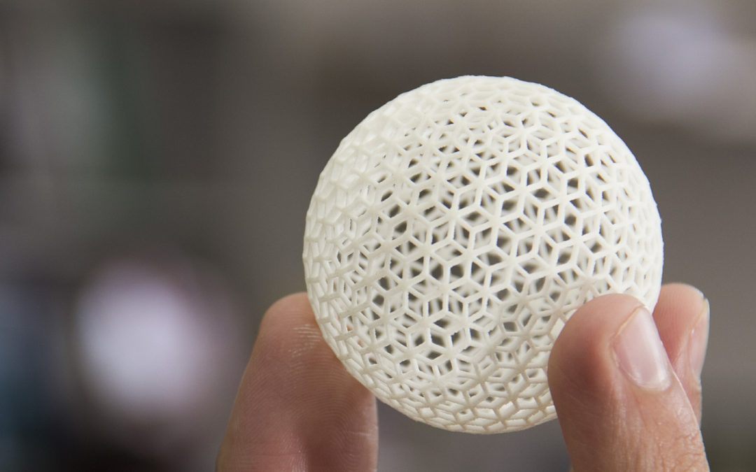
Reshaping Antenna Design with 3D Printing
As we discussed in a previous post, before we can manufacture, we must prototype. For this step in the process, we are beginning to explore additive manufacturing, or as it’s more commonly known, 3D printing.